 The Vox Solid State AC30SS Amplifier - A Look "Under the Hood"
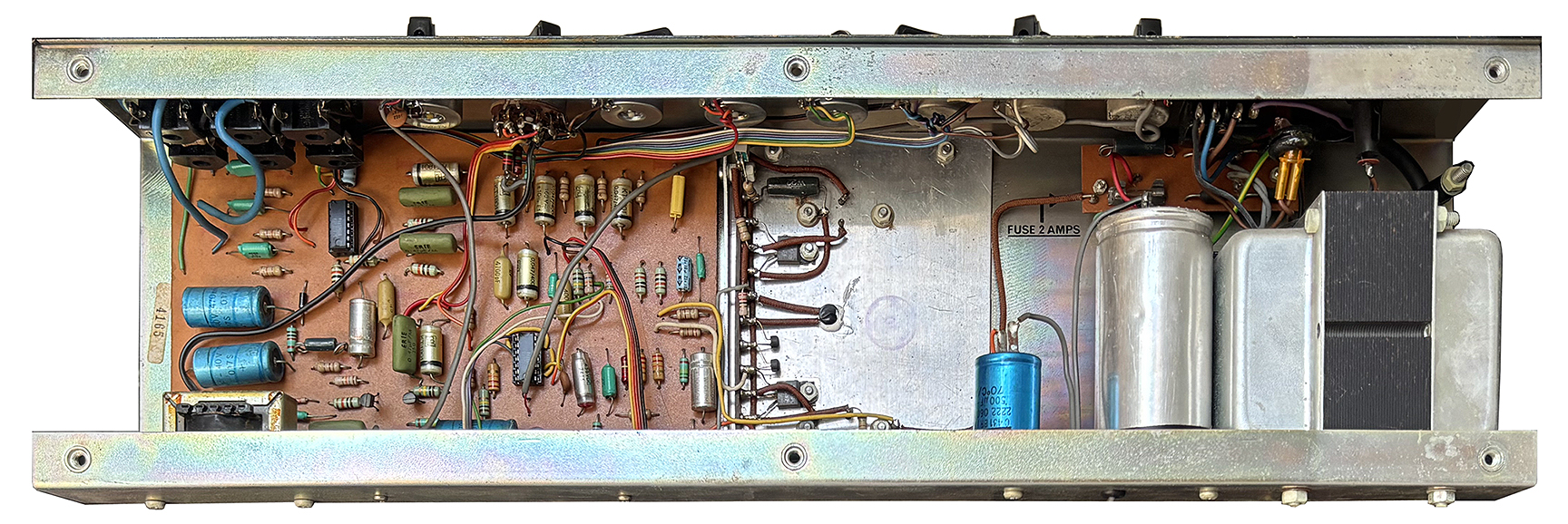
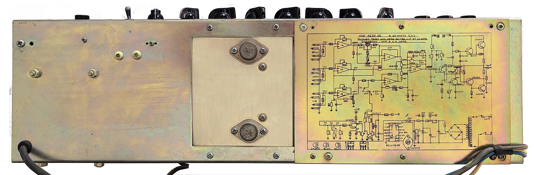 Fig.1 - Front and rear views of the Vox AC30SS chassis including the screen printed schematic
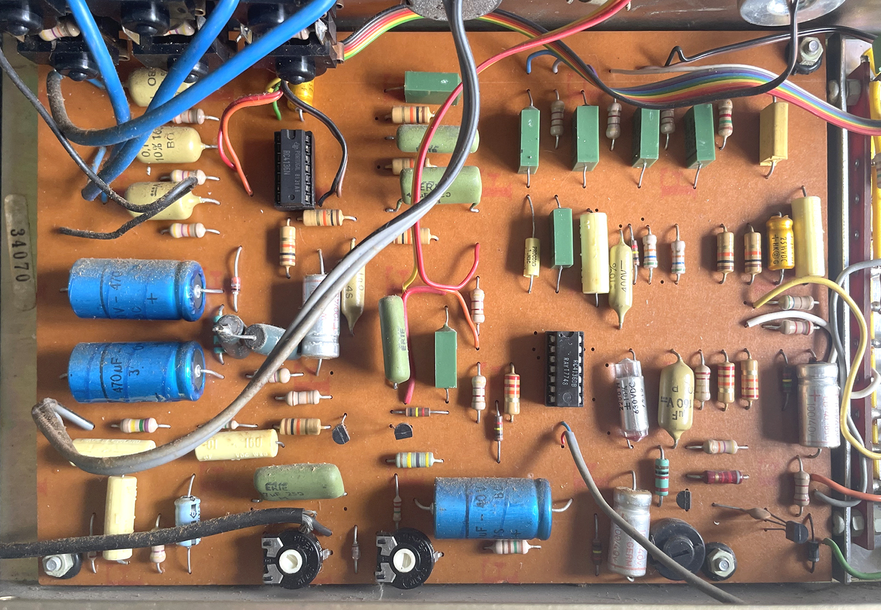 Fig. 2 - Vox AC30SS main circuit board - component side
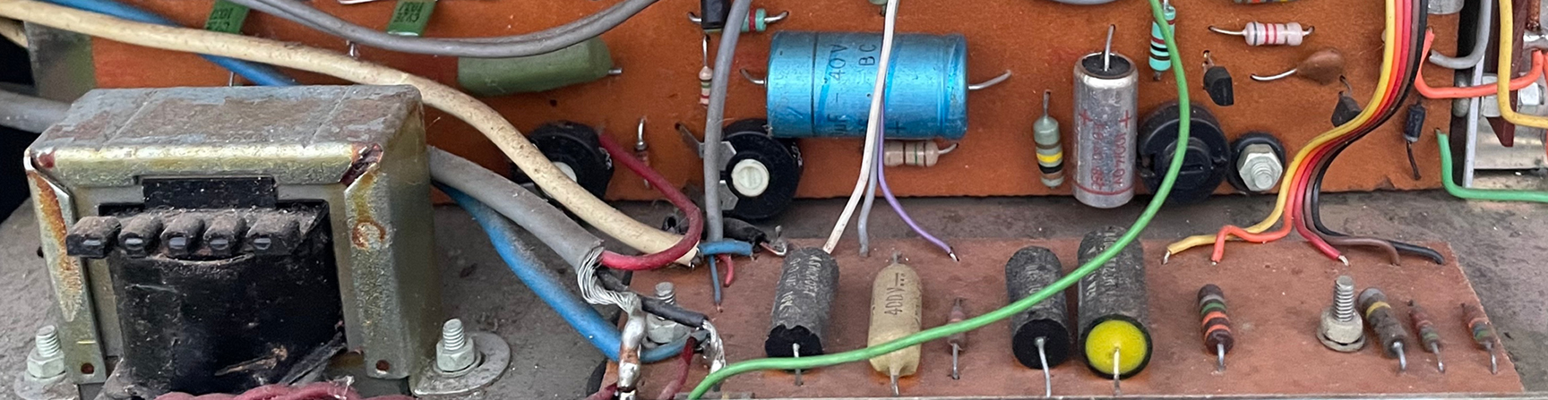 Fig. 3 - AC30SSR reverb circuit board and drive transformer
Launched in 1977 by Dallas Musical Industries (DMI), the Vox AC30SS was built at the expansive DMI manufacturing facility in Shoeburyness, Southend-on-Sea, UK. Even after Rose-Morris acquired the Vox brand from DMI in 1978, Dallas remained as the manufacturer, producing Vox amplifiers, including the AC30SS and SSR, under contract for Rose-Morris. The AC30SS shown on this page is a later version from the Rose-Morris era so it may exhibit some differences when compared to the earlier versions.
Chassis
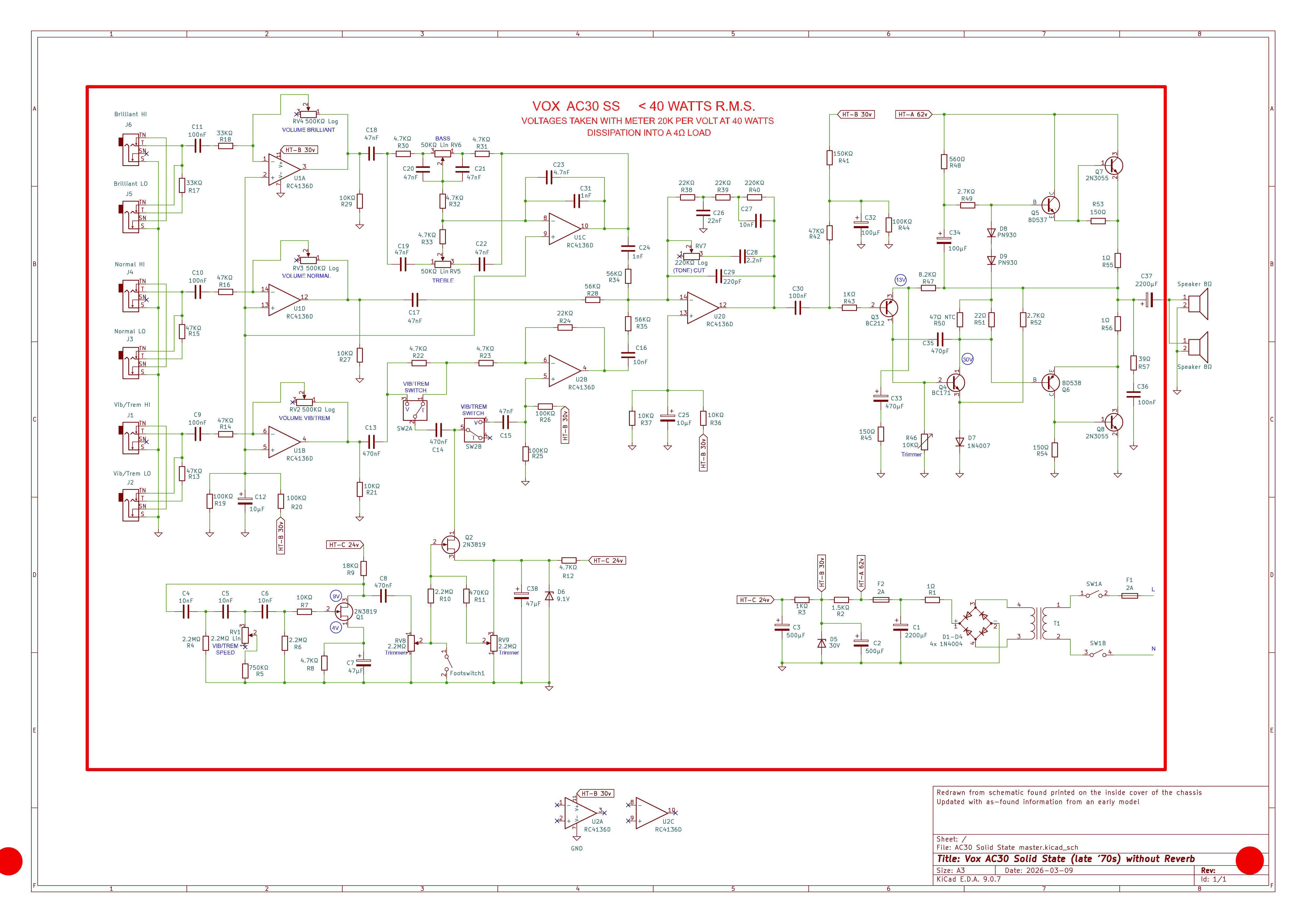
Both the Vox AC30SS and AC30SSR featured a "C" shaped steel chassis with a removable access panel. This panel not only provided access to the foil side of the main circuit board but also conveniently displayed a screen printed schematic of the amplifier (see Fig. 1 and Fig. 4).
Main Circuit Board
Much of the circuitry of the AC30SS, including the preamp, Vib/Trem effect and drive circuits for the power amplifier were located on the main circuit board (see Fig. 2). The controls were mounted to the chassis, not the main circuit board. The controls were interconnected to the main circuit board with lead wires.
RC4136 Op-Amp
In 1968, Fairchild Semiconductor introduced the μA741, a landmark operational amplifier (op-amp). It combined 25 transistors and supporting circuitry into a complete audio amplification circuit housed in a compact 8-pin integrated chip. By the mid-1970s, further miniaturization allowed four discrete and upgraded μA741 circuits to be consolidated into a single 14-pin package: the RC4136 quad op-amp. Vox utilized two of these chips (labeled U1 and U2 on the schematic) in their AC30SS and AC30SSR models. This significantly streamlined the layout of the main circuit board. To simplify maintenance, the RC4136 chips were mounted in sockets on the main circuit board.
Here are the functions of the RC4136 quad op-amp chips.
● U1A - Initial gain stage for the Brilliant chanel
● U1B - Initial gain stage for the Vib-Trem channel
● U1C - Gain recovery for the Treble and Bass controls
● U1D - Initial gain stage for the Normal channel
● U2A - Reverb circuit (AC30SSR only)
● U2B - Vib-Trem circuit
● U2C - Reverb circuit (AC30SSR only)
● U2D - Final preamp gain stage for all three channels
The use of the RC4136 quad op-amp in the circuitry of the AC30SS and AC30SSR amplifiers precludes any possibility that these models were designed years earlier by either JMI or Thomas Organ. The RC4136 went into production in the mid 1970's, long after JMI or Thomas Organ ceased producing Vox amplifiers.
Vib-Trem Circuit
The Vox AC30SS and AC30SSR feature a solid-state recreation of the classic Vib-Trem circuit originally found in the tube-powered AC30.
In general terms, the vibrato effect in a guitar amplifier is produced by applying a low-frequency oscillation (LFO) —typically a 3 to 10 Hz sine wave— to the signal from an amplifier's preamp stage. This causes the signal to cyclically shift above and below its fundamental frequency. The frequency of the LFO dictates the speed of the effect (e.g., 3 hz for slow vibrato and 10 hz for fast), while the amplitude (intensity) of the LFO determines the depth of the pitch variation.
The AC30SS Vib-Trem circuit used a three-pole RC network (R4-–R6, RV1, and C4-–C6) to produce an LFO. By adjusting the panel mounted "Speed" control (RV1), one can sweep the LFO frequency from 3 Hz to 10 Hz, applying vibrato to the signal from op-amp stage U1B. Q1, a 2N3819 JFET transistor, provided the gain to power the LFO. Q2, a second 2N3819 J-FET, controlled the depth of the vibrato and tremolo effects. To ensure these transistors operated correctly, two 2.2 MΩ internal trim pots (RV8 and RV9) were provided to adjust their bias levels as needed.
For the AC30SSR, the "Vib-Trem" knob (SW2) was replaced by a six-position rotary switch that offered three preset speeds each for the vibrato and tremolo effects. This change allowed the "Reverb" control to occupy the panel location previously used by the RV1 "Speed" control.
Reverb
In later production, Vox introduced the solid-state AC30SSR with built-in reverb. This system utilized an Accutronics 4AB2A1B dual spring, medium-delay tank with 150Ω input and 2250Ω output impedances. To support the reverb, a separate PCB and a drive transformer were mounted to the floor of the chassis (see Fig. 3).
Power Supply
Vox AC30SS and AC30SSR power transformers were built with a 240 VAC primary winding with little evidence to suggest that a 120 VAC version for the US or Canada was ever produced. Thomas Organ retained the North American manufacturing and distribution rights for Vox throughout the 1970s, effectively blocking the importation of UK made Vox amps to the US.
The transformer’s single secondary winding fed a bridge of four 1N4004 diodes and a 2200 µF filter capacitor to generate a single +62 VDC rail for the power amp. This supply was then stepped down through a resistive ladder that included two 500 µF filter caps and a Zener diode to create +30 VDC and +24 VDC taps for the main circuit board components.
The power supply featured two 2A slow blow fuses for protection: one externally mounted on the control panel to safeguard the primary winding and a second internal fuse to protect the secondary.
Power Amplifier
The AC30SS and AC30SSR employed a quasi-complementary power amplifier circuit adapted from the Vox Escort 30 that used two 2N3055 NPN output transistors to emulate a standard NPN-PNP push-pull pair. It accomplished this by using a traditional Darlington pair (BD537 NPN driver transistor + 2N3055 NPN output transistor) for the upper half of the wave and a Sziklai pair (BD538 PNP driver transistor + 2N3055 NPN output transistor) for the lower half of the wave. This Sziklai pair configuration effectively simulated a high-power PNP output transistor, bypassing the high costs and reliability issues associated with early PNP power transistors. The audio signal from the output transistors then passed through a 1000uf electrolytic capacitor before reaching the speakers. This capacitor was critical to isolate the amplifier's DC biasing voltages from the speaker output. Without this capacitor acting as a barrier, the DC biasing voltage from the 2N3055 output transistors would instantly burn out the speaker's voice coil.
AC30SS Schematic Download
Please click here to download a free and remastered copy of the Vox AC30SS, including part numbers and electronic values.
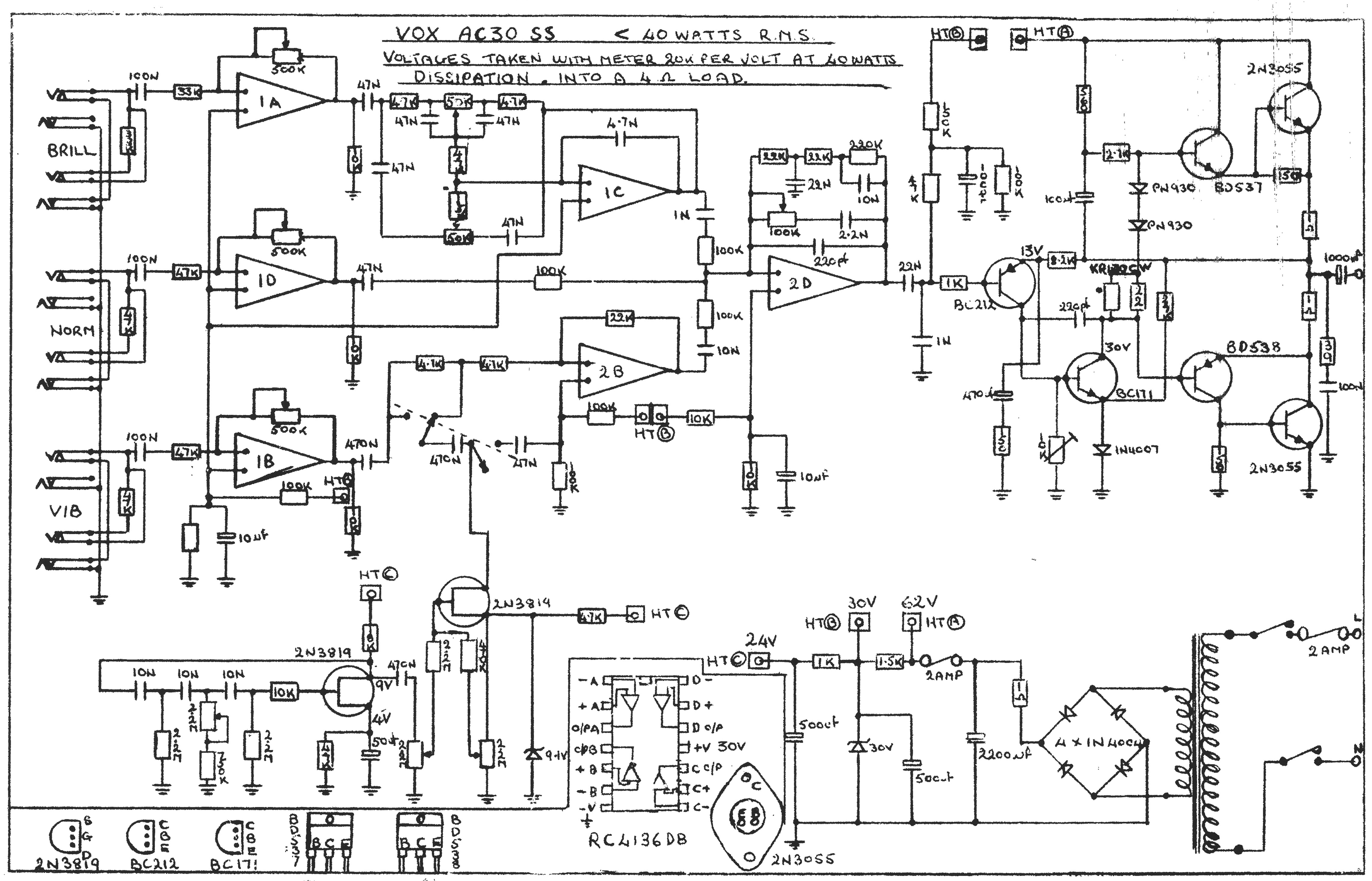
Fig. 4 - Vox AC30SS Schematic
|
3_Footer

Photos and editorial content courtesy Gary Hahlbeck
Any and all material presented herein is protected by Copyright.
© 1998 - 2026 The Vox Showroom, all rights reserved
The images and editorial content in this web site may not be copied or reproduced
in online auction sites such as eBay, Reverb and Craig's List. Sellers may provide a link
to the Vox Showroom web site if they wish to refer to this copyrighted material.
|
URL: https://www.voxshowroom.com/uk/amp/ac30ss_hood.html
|