 The Vox Solid State Escort 50 Bass Amplifier - A Look "Under the Hood"
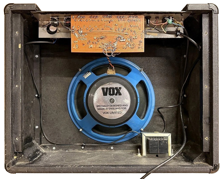
Cabinet
In contrast to the premium finger-jointed, 13-ply Baltic birch cabinets manufactured by Vox in the 1960s, the Escort 50 Bass enclosure used simpler butt-jointed particle board reinforced internally with heavy wooden cleats.
Chassis
The Escort 50 Bass featured an inverted "L" shaped, 16-gauge steel chassis that anchored most of its circuitry. Beyond mounting the electronic components, the chassis also functioned as a heat sink for the output transistors. The power transformer was the only electronic component not mounted to the chassis; instead, it was secured directly to the bottom of the cabinet.
Circuit Board
A single phenolic printed circuit board housed the preamp circuit, tone controls, power amp drivers, and power supply (minus the mains transformer). This board was secured to the chassis by the five PC mount potentiometers. Screws on each end of the chassis fastened it to the amplifier cabinet.
Single Rail Power Supply
Configured for worldwide use, the Escort 50 Bass relied on a power (mains) transformer with a tapped primary winding to accommodate multi-voltage operation at 115, 220, or 240 VAC. Its single, untapped secondary winding fed an IN5404 diode bridge rectifier in conjunction with a 1000 µF smoothing capacitor to generate a +80 VDC rail to supply the power amplifier circuit. This +80 VDC rail voltage was then stepped down to +30 VDC to power the preamp stage via a 1k 5W resistor and a 30V Zener diode.
The Escort 50 Bass had a 1.6AT (slow-blow) fuse located on the control panel.
50 Watt Quasi-Complementary Power Amplifier Circuit
The Escort 50 Bass employed a quasi-complementary power amplifier circuit using two 2N3055 NPN output transistors to emulate a standard NPN-PNP push-pull pair. It accomplished this by using a traditional Darlington pair (BD537 NPN driver transistor + 2N3055 NPN output transistor) for the upper half of the wave and a Sziklai pair (BD538 PNP driver transistor + 2N3055 NPN output transistor) for the lower half of the wave. This Sziklai pair configuration effectively simulated a high-power PNP output transistor, bypassing the high costs and reliability issues associated with early PNP power transistors. The audio signal from the output transistors then passed through a 1000uf electrolytic capacitor before reaching the speakers. This capacitor was critical to isolate the amplifier's DC biasing voltages from the speaker output. Without this capacitor acting as a barrier, the DC biasing voltage from the 2N3055 output transistors would instantly burn out the speaker's voice coil.
Preamp Circuit
The entire preamp circuit, including the tone controls, was powered by a single RC4136 quad opamp. The RC4136 included four independent amplification circuits in a compact 14-pin DIP (dual in-line) package. The RC4136 significantly streamlined the layout of the circuit board and completely eliminated the need for discrete transistors in the preamp circuit.
Schematic
Download the factory schematic for the Escort 50 Bass by clicking here.
|
3_Footer

Photos and editorial content courtesy Gary Hahlbeck
Any and all material presented herein is protected by Copyright.
© 1998 - 2026 The Vox Showroom, all rights reserved
The images and editorial content in this web site may not be copied or reproduced
in online auction sites such as eBay, Reverb and Craig's List. Sellers may provide a link
to the Vox Showroom web site if they wish to refer to this copyrighted material.
|
URL: https://www.voxshowroom.com/uk/amp/escort50bass_hood.html
|